In the neighboring lab a group of friends (Siam and Bridget) are working on genetically engineering microorganisms to produce fuel or other useful organics. A lot of their research revolves around rapidly growing various strains of bacteria under a multitude of conditions to study various gene expressions.
For a lot of their work they are currently using reactors like this one:
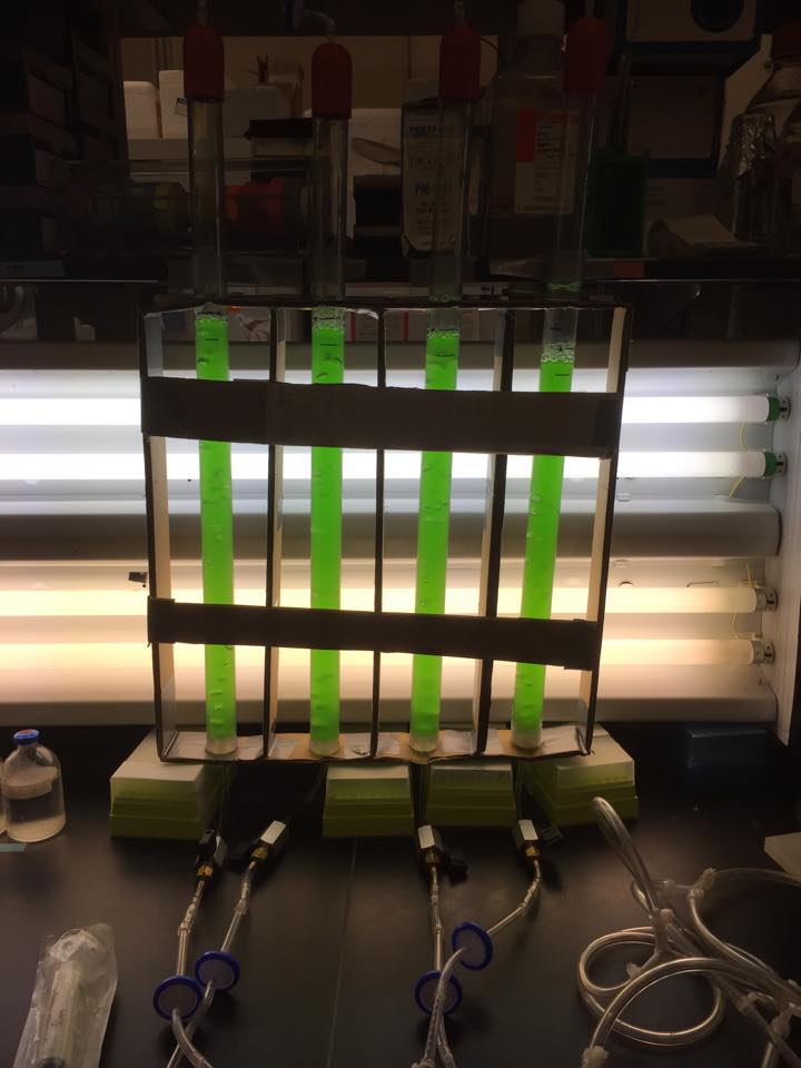
Each transparent plastic tube is filled with growth media (and periodically refilled to make up for evaporation or food being used up by the organism). It is kept on specific temperature cycle, irradiated with white or red light under various intensities and day-night cycles, and pumped with CO2+air mixtures at specific proportions. It is periodically partially drained and refilled with growth media so that the colony can continue growing (this step seems to be required also for obtaining the fuel being produces by the organism).
The size permits harvesting large amounts of biomaterial which can be important for certain tests. But in other cases it just slows work down. Working with the reactor requires quite a bit of manual labor.
Siam (a bioengineer? environmental engineer? warlock? I should ask him…) has been thinking on and off since undergrad about making a fancier automated reactor. While working out some data logging project for the current reactor with Bridget (a biologist? environmental engineer too? druid? sorceress?) we all decided that it might be fun to try to build such a contraption (even if it was not clear yet what exactly the device will be).
We have been working on the project a few hours each month for a while, but it is currently shelved until we can find a good chunk of time for the final push. In the meantime I will try to describe what we have now:
Firstly and lastly, the new reactor had to permit rapid evaluation of a given strain (or multiple strains) under various conditions.
We do not need the large containers any more - an extremely small “well” suffices for growing our organism. A future version might use a microplate, but for ease of working with our hobbyist level electronic and mechanic components we decided to stick to something bigger.
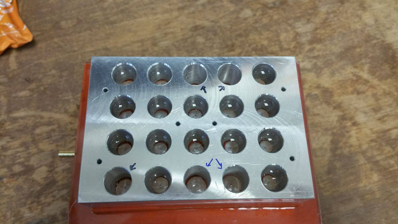
The block contains 20 holes (each of about \(2 cm^2\) ). It is metal so that we can have efficient temperature control. A transparent acrylic plate will be attached to the bottom to ensure light from red LEDs can pass through.
- Why not illuminate from above and have a blind hole for the well? That way you remove the complexity of attaching two materials together, especially important for ease of cleaning of the reactor. - Then we do not have easy access from above for other instruments as the LEDs are there now. We do not have an opening to easily drain the fluid (see below). And we need to shake the container to ensure aeration instead of pumping from the opening (also loosing the control over the CO2/air ratio).
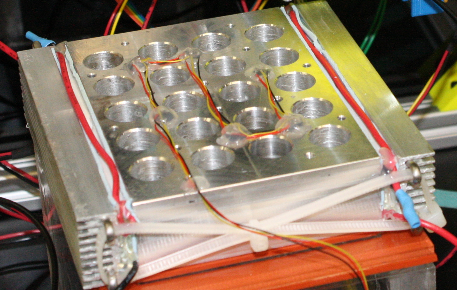
We need to be able to drain the well and ideally we want also to be able to pump a mixture of CO2 and air in it. This can be achieved through a valve opening in the acrylic bottom - positive pressure pumps the gas in; negative pressure sucks the liquid out in a big container under the block of wells.
The first attempt at a one-way valve was a complicated layering of laser-ablated acrylic with a small piece of plastic film in a void formed in the center of the layering. The air going to the well would push the film against a rough surface and pass around it, but the water would push the film against a flat surface in the other direction hence closing the channel.
It worked horribly.
Instead we just used small-diameter needles. The surface tensions of the liquid does not permit the water to drip out under just gravity. But a negative pressure would be able to suck the water out and force it to drip down and a positive pressure would be able to force air in. The red LEDs were attached next to the needles. We might not even need the needles with a good laser cutter to make the small holes directly in the acrylic.

The laboratory already provides outlets for the negative pressure and the CO2+air mixture. We use a couple of solenoids to direct the flow as appropriate.
For temperature control we attached OneWire temperature sensors in between the wells and thermo-electric plates (Peltier plates) on the sides, all run by a naive PI loop. Running the plates at no more than 30% of their specs already permits us to work in the 20C to 40C interval.
Finally we have an xy-table with instrumentation on top of the wells. It will be:
- Adding growth media through a dripper after draining - this includes measuring the height of the media using the reflection of a laser on the liquid surface onto a photoresistor;
- Measuring the growth of the organism by measuring what amount of light is transmitted trough the media with a light sensor;
- Irradiating the sample with UV in order to induce mutations;
- A suspendable needle to take a sample out - after a mutation has been induced by the UV and detected as beneficial by measuring the growth the needle will spread the content of the lucky well to all other wells, hence leading to guided evolution.
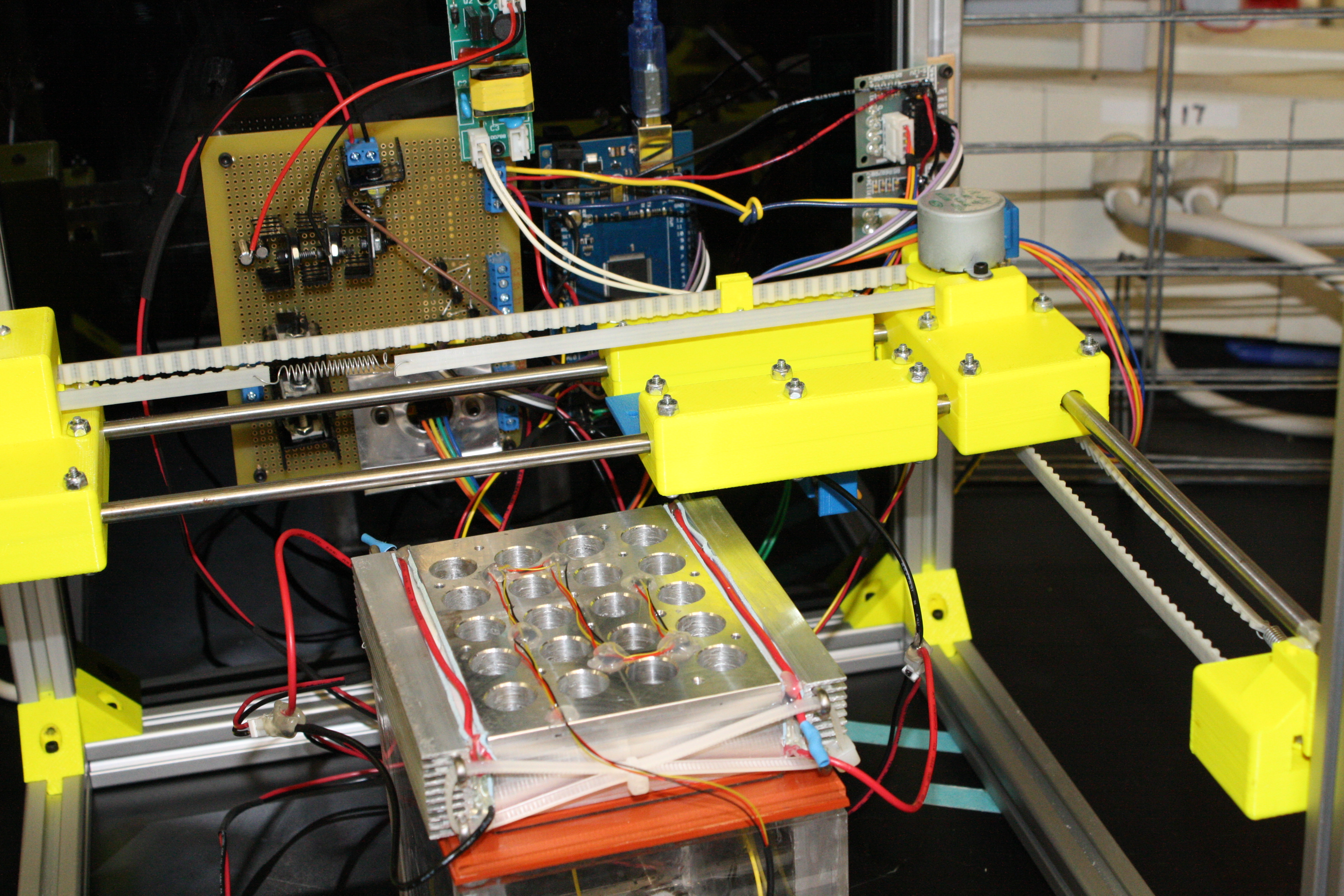
This all is controlled by a few FETs and motor drivers driven by an Arduino. A web interface was deployed on a Raspberry Pi that controls the Arduino and provides for easy setup and tracking (from anywhere in the world) of experiments.
The serial connection between the Arduino and the Raspberry Pi was quite unreliable so we took measures to ensure robustness. And we went way overboard… The commands from the Raspberry Pi to the Arduino and the measurements from the Arduino to the Raspberry Pi are sent together with a disproportionately big checksum. On repeated failed checksums or timeouts the connection is severed at the USB driver level by the Raspberry Pi and reestablished. Each failure is logged for debugging. The protocol itself is human readable for ease of developing. If one wants to, an entire experiment can be ran from a terminal connected directly to the Arduino.
However, the software on the Raspberry Pi provides a much nicer interface:
- A web interface build from scratch with the
CherryPyframework; - A log of the entire history of the reactor in an
SQLitedatabase - including arbitrary notes or other metadata attached to any timepoint in the logs. - Scheduling of per-well, per-row-of-wells, or global events for the reactor like repeated draining and refilling, time-dependent illumination, time-dependent temperatures, UV irradiation, and measurements of growth;
- Visualizing the data in aggregate or per-well with interactive plots through the
bokehlibrary; - Storing multiple strains or reactor configurations;
- Custom plots and data export;
- Emailing and texting on important events.

All of the described components have been at least partially build and work in mock tests. Hopefully in a few months we will be able to spare a chunk of time to finish the project.
The source code is available on Github.
