For the moment it is only ECG.
A few months ago I started working on a DIY EEG machine with a bio-major undergrad friend of mine. Here is my attempt at writing a lab notebook for the project after the fact.
The First Prototype
The very first prototype was based on an instructables.com page. The project described there has some arbitrary sounding choices (especially the notch filters schematics), however it is a nice starting point and I am grateful to the author for the inspiration.
What we decided upon with my friend was the following setup:
- a first stage - an instrumentation amplifier of gain 100x (or 1000x, but that was too much) (AD620 initially, something more modern later)
- a second stage - an active low-pass (around 30Hz), high-pass (around 5Hz), and notch (50 or 60Hz)
filters based around LMC660 quad
op-amp (but you can find cheaper and better chips)
- the low and high pass filters were slightly underdamped Salen-Key filters
- the notch filters comes from here
- the order of the filters was easily changeable with jumper cables
Yet it did not work…
We started testing on ECG signals as they are much stronger than EEG ones.
The output from the first stage was always saturated due to the DC difference between different parts of the body. Occasionally we would get a signal, but it would quickly disappear as the electrodes charge and saturate the instrumentation amplifier.
The high pass filter was, therefore, useless as its input was already clipped. We had to remove the DC component before it enters the instrumentation amplifier. We decided to use the simplest passive high pass CR filter on both inputs before the instrumentation amplifier. These application notes nicely present the details albeit in somewhat different context. There is one important issue to be remembered. If the resistances in the passive filters are too big then the potential differences due to bias currents from the amp could become an issue. So check the datasheet for your instrumentation amplifier. Other than that there are no restrictions on the components.
This was the single change with greatest effect on the final signal quality. After that we actually got usable ECG signals.
The electrodes
The electrodes initially were just quarters soldered to unshielded wires. Then we bought Neuroline(TM) cup electrodes from Ambu. There was no great difference in the signal quality (especially given that these electrodes also have unshielded wires), however when we started using conductive gel (also from Ambu), the signal to noise ratio rose dramatically.
For best signal quality we just put the ground electrode and one of the differential electrodes in the mouth, while the other is on the chest.
Persisting issues
The biggest issue currently is the 50-60 Hz noise coming from the mains electricity. If the electrode wires are too long the noise completely drowns the signal. We had to be extremely careful with grounding all our circuits as well, because in the noisy environment in which we worked even one floating ground caused bizarre high-frequency noise from various equipment in the room.
We were measuring the noise with respect to different electrode configurations, filter configurations, gain levels, etc, (with varying rigor) before deciding on the changes to the circuit in order to have the simplest working solution.
The modification we plan for the next version are:
- passive high pass filter before the instrumentation amplifier (as currently)
- nice instrumentation amplifier (as currently)
- integrated 8th order low pass filter after the instrumentation amplifier (no low pass and notch filter which are present currently)
- right-leg driver (missing currently)
- shielding for the electrode wires (missing currently)
Some other details
The power supply is a 9V battery divided into a bipolar supply with a 741 op-amp.
In the pictures the case is not finished. In the final version the electrodes would be terminated with an audio jack, not directly soldered to the circuit. In the same way, the output would be accessible through and audio jack instead of the currently used jumper cables.
In pictures
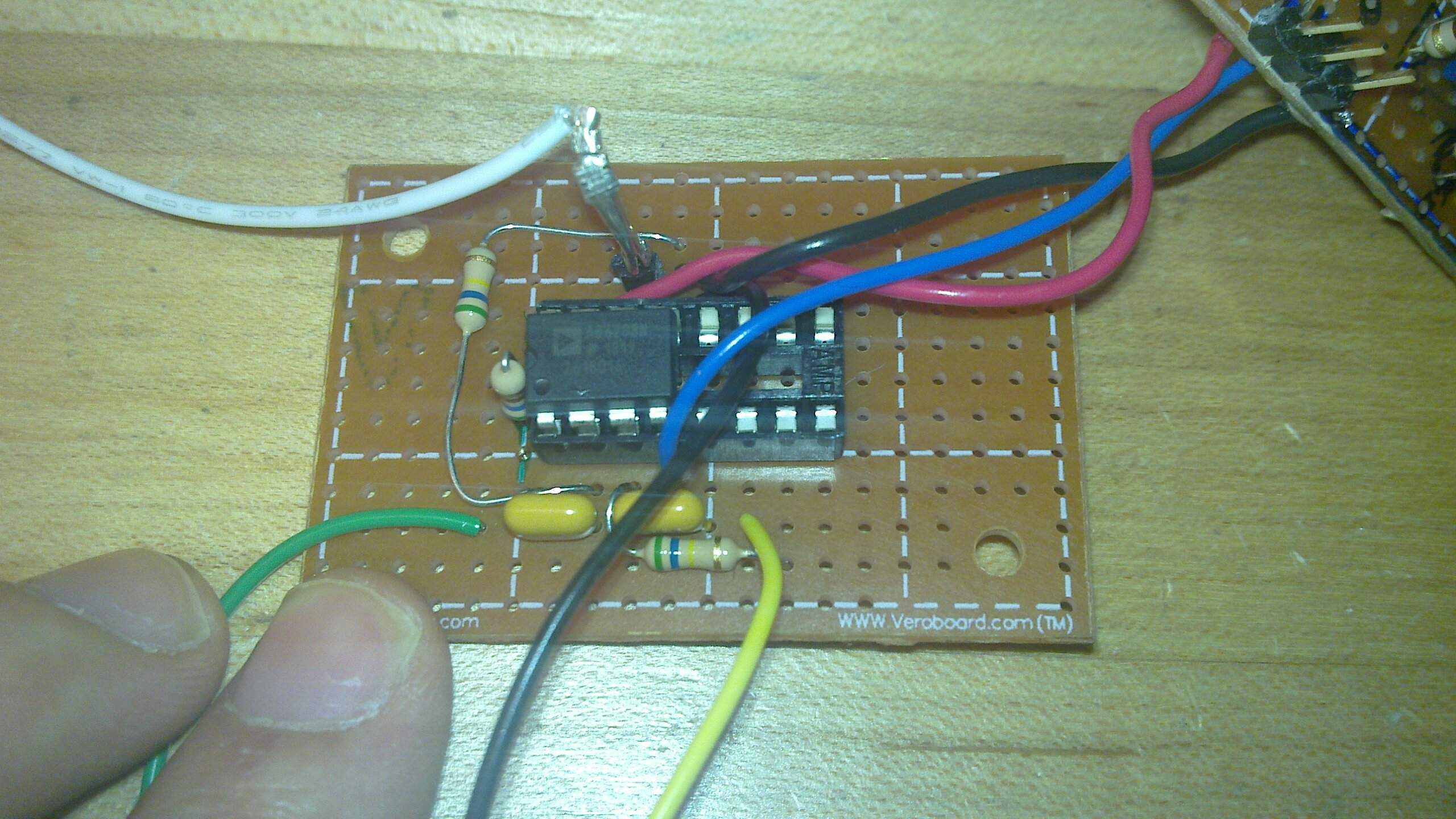 The instrumentation amplifier in the first stage. The capacitors and
resistors at the bottom are the passive high-pass filters.
The instrumentation amplifier in the first stage. The capacitors and
resistors at the bottom are the passive high-pass filters.
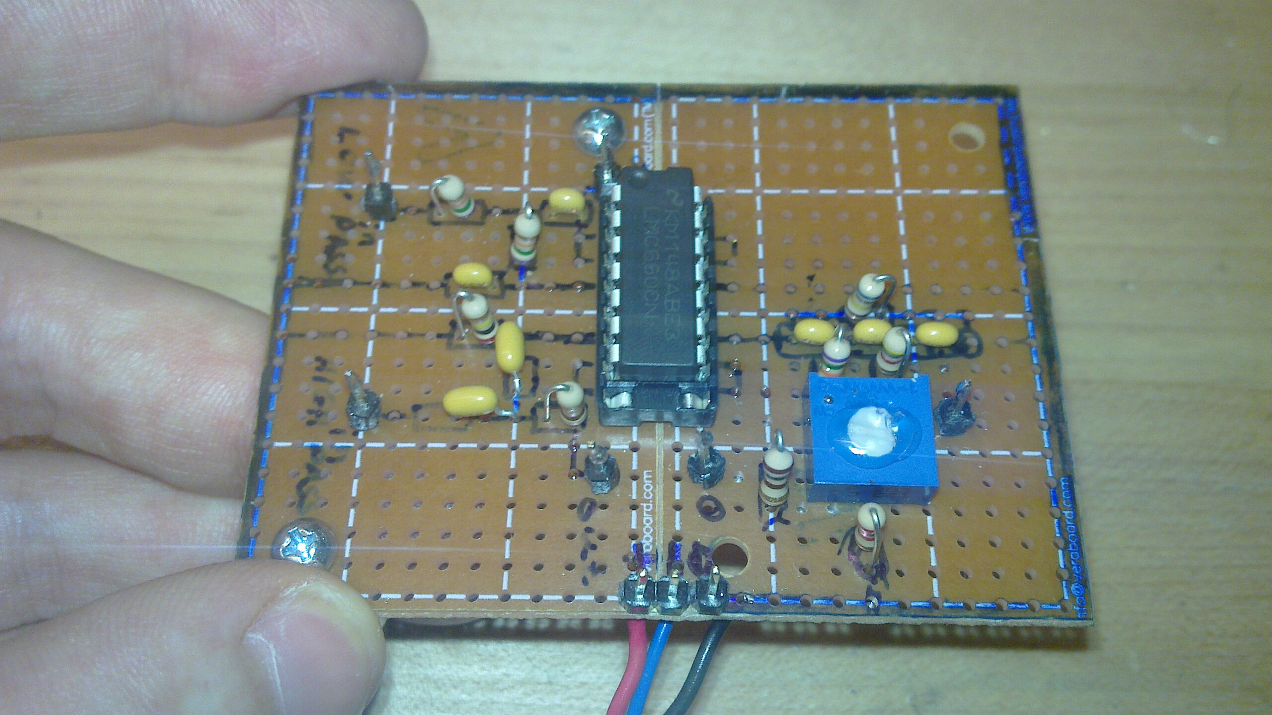 The three filters in the second stage. Their order can be interchanged
with appropriate jumper cables. On the right is the notch filter.
The three filters in the second stage. Their order can be interchanged
with appropriate jumper cables. On the right is the notch filter.
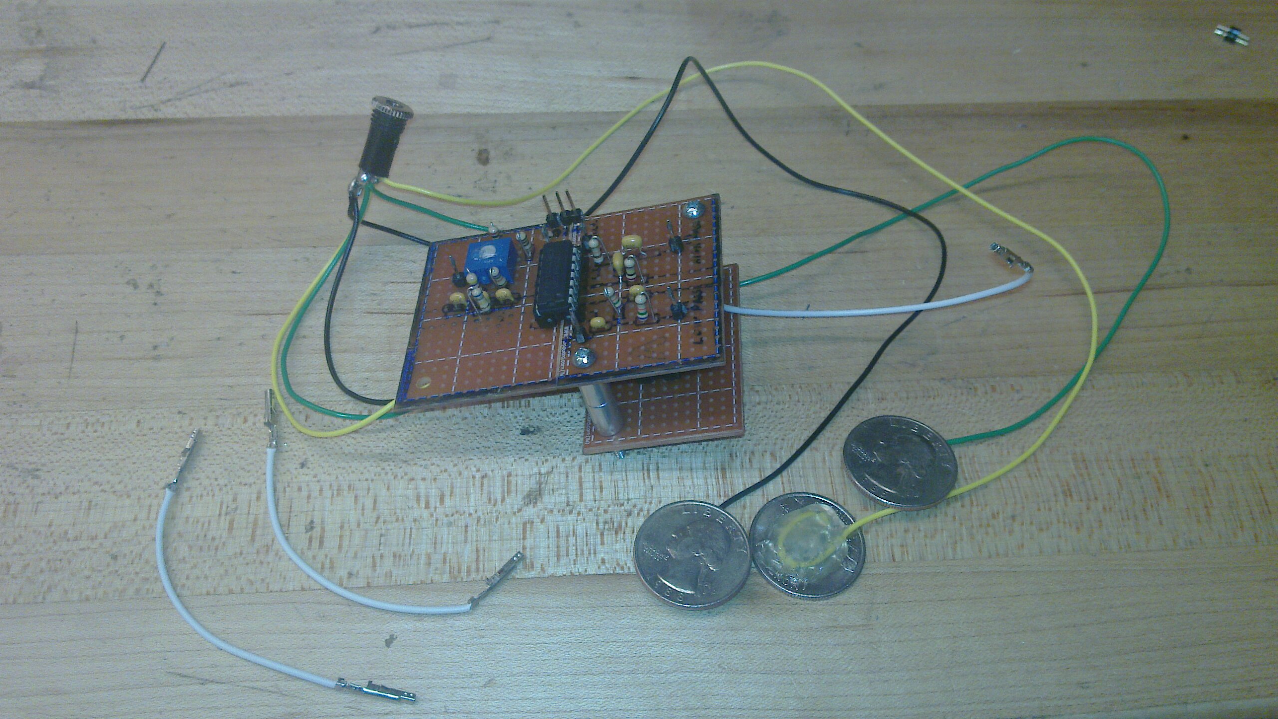 The full machine, including coin electrodes. There is an audio jack in the
upper left meant to be used when the electrodes get an audio jack terminal.
The full machine, including coin electrodes. There is an audio jack in the
upper left meant to be used when the electrodes get an audio jack terminal.
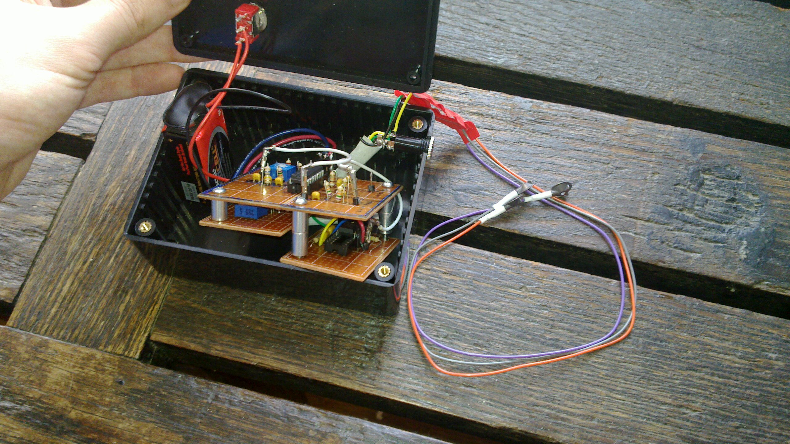 The almost-final casing with the Neuroline(TM) electrodes.
 There should be a second audio connector for the output. And the electrodes will be
on an audio jack in the first connector instead of directly soldered.
There should be a second audio connector for the output. And the electrodes will be
on an audio jack in the first connector instead of directly soldered.
 And a picture of an actual signal trace.
Many thanks to Holly Mandel for suggesting the project and working on it with me.