My favorite way to teach a subject is to present the math or physics under study as the tool empowering you to do magic (the Arthur Clarke type of magic). Moreover, when teaching, the best type of magic is the flashy beautiful whimsical magic. This has led to the creation of a number of jewelry-styled projects that colleagues and I have used to excite students to view STEM as the creative medium it is.
They are great for teaching physics: kinematics of the motion sensor; Euler angles and other representations of rotations; spectra and intensities in the physics and biology of color perception.
This overlaps with math: vectors as used in kinematics; filters, response functions, and Fourier transforms used as an artistic medium that turns the detected motion into a beautiful colorful LED pattern.
And finally, there is computer science: event loops; functions as objects; understanding of pointers and redirection in a realistic and practical project; even the notion of frame-buffers.
The best part is that this vast set of topics can be approached completely independently - use the standard firmware and just teach kinematics; upload the bare-bones firmware and study event loops; or stop in between and experiment with mathematical filters that visualize the motion in a more interesting pattern of LED lights.
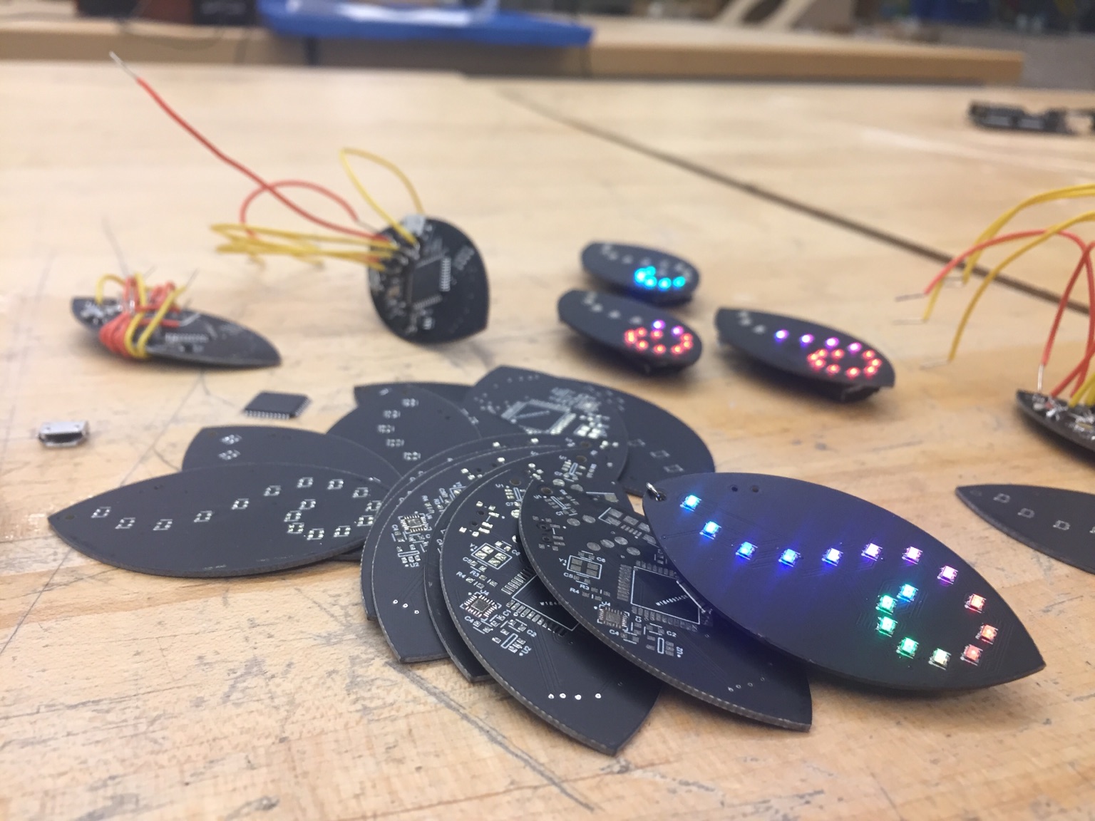
This led to the creation of (among others) a set of motion sensing LED earrings/keychains. The project was developed with an environmental engineering colleague of mine also interested in STEM outreach. If you are interested in how we used similar projects in educational settings see the Engineering Day website.
Below I describe the tools we used, in the hope that we could convey how easy it is to take the step from breadboarded toys to professional looking toys. There are a couple of important parts to it:
- trivially easy to use circuit design and PCB layout software
- online small-batch circuit board printing shops
- surface mount components that are easy to solder for inexperienced hobbyists
- simple firmware - concise and legible, showcasing vanilla CS ideas, without being too limiting
Circuit design and PCB layout software
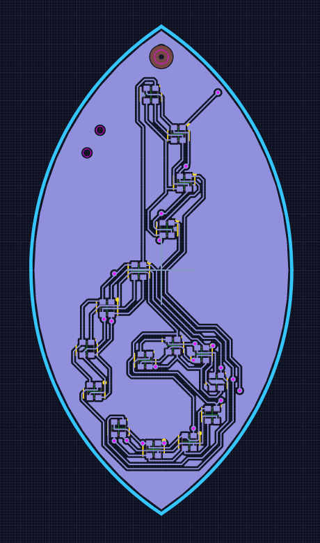
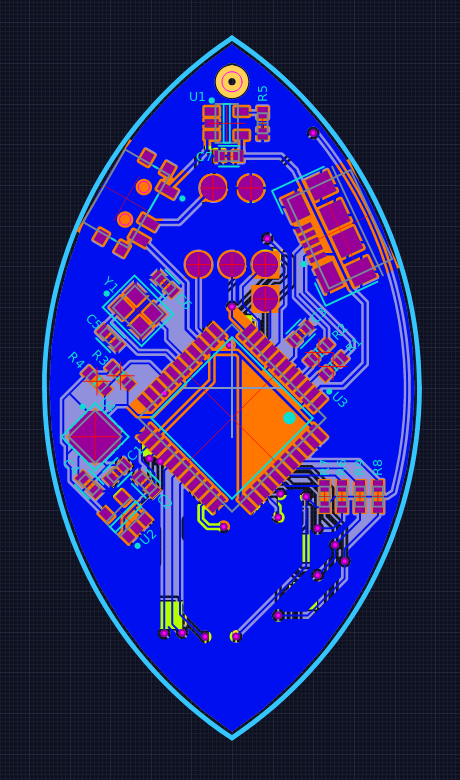
This is a tool that lets you draw a circuit diagram. However, it also permits you to assign an actual “footprint” for each component of the diagram and helps you place these footprints on a virtual printed circuit board. It does many checks for you, ensuring that the traces you draw on the printed circuit board are realistically sized, etc. Once you are done with your CAD model of the PCB, you can submit the project files to one of the many PCB manufacturing services and get 10 or 1000 of them delivered to you fairly cheaply.
Upverter is an online PCB layout software. It is the Google Docs of CAD PCB design. It is a great first tool for hobbyist: it has a much gentler learning curve, although the ease of use might encourage sloppiness. It is the tool we used for this project, and you can clone all of the project files from the inset below:
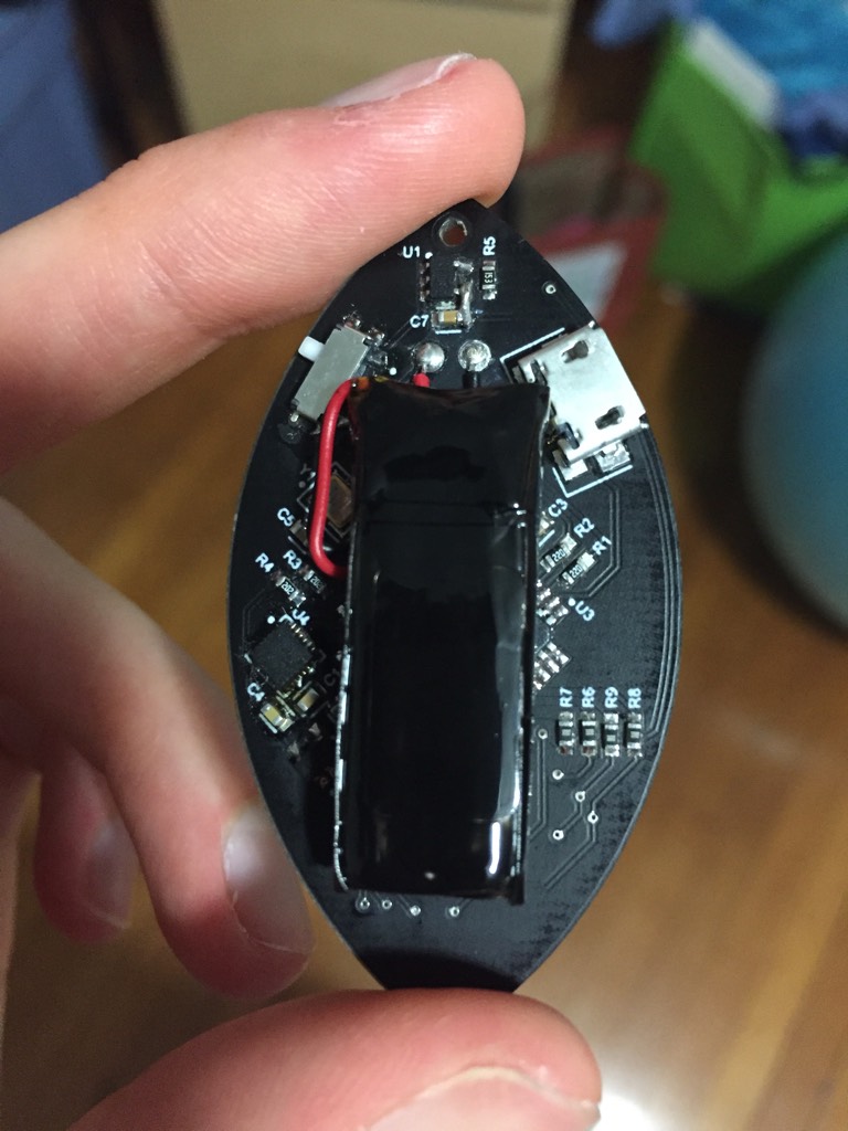
We have the simplest battery charger, the simplest motion sensor, and the simplest USB-capable Arduino-compatible micro controller. All of them are wired exactly as in their datasheet examples.
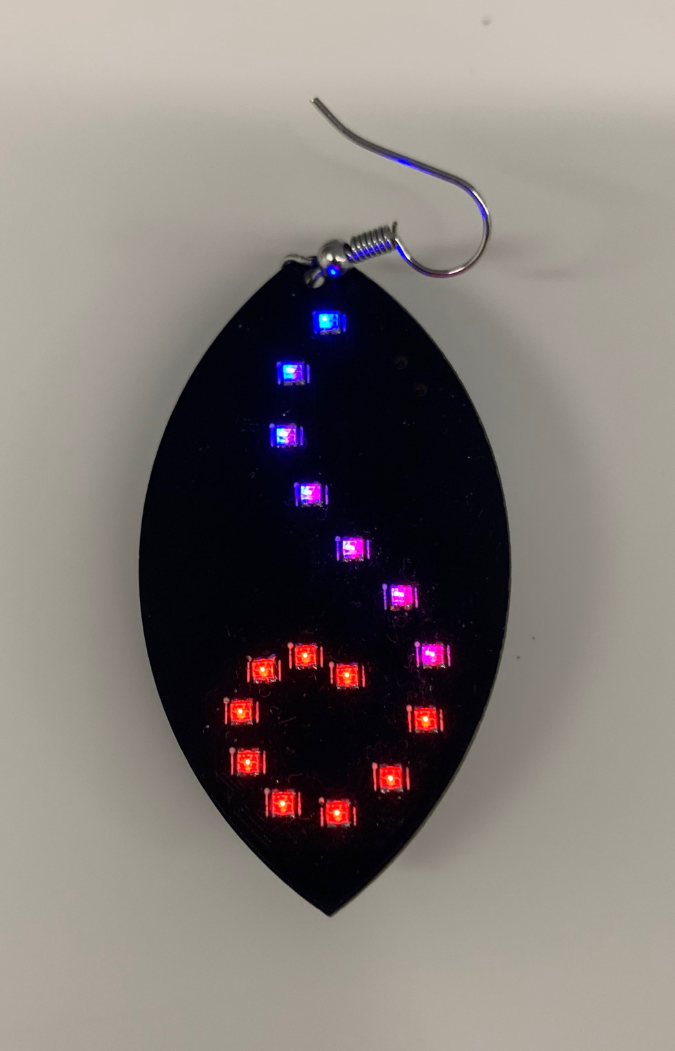
The LED themselves are wired in a multiplexed grid: instead of using a pin per LED, we arrange them in a grid, with each column having the same anode pin and each row having the same cathode pin. This drastically lowers the required pin-count (we need only 4+12=16 pins for the 4*12=48 LEDs), however only one LED can be on at a time, which means we need to use persistence of vision techniques: we switch between LEDs very quickly, creating the illusion of having them all on at the same time.
The LEDs themselves are packaged with a red, green, and blue LED in the same package. We have 16 such packages soldered to the board in a vine-like pattern. The pattern dictated the use of a suboptimal choice of pins that made the software slightly more complicated.
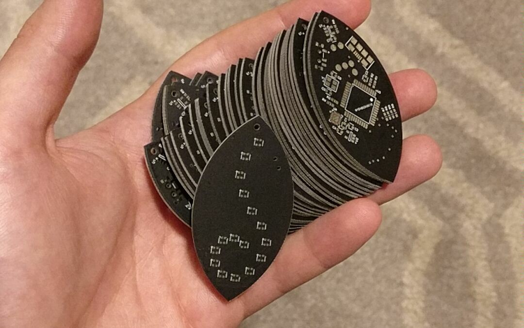
The front and back of the earring PCB and a picture of the delivered boards.
Surface mount soldering
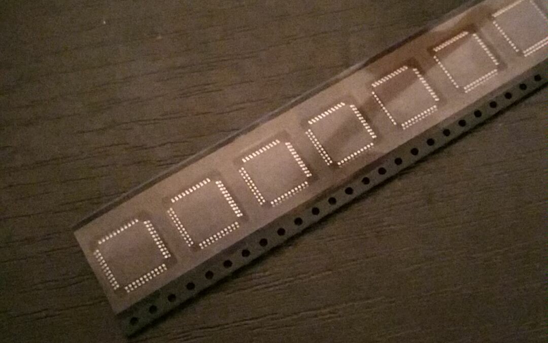
The idea might sound terrifying to hobbyist used only to through hole components. However, with flux and a hot air gun, simple surface mount work can be easier than through hole work. For TQFP components like the microcontroller I use a fine chisel tip soldering iron with flux, while for everything else I use a simple heat gun technique: add flux, tin everything, clean and add new flux, place components, heat until settled:
Surface mount soldering can be easy.
The firmware
There are a number of interesting ideas that can be taught with this simple firmware. Naturally, the notion of an event loop is one of them.
Moreover, in our particular case we have a cute way to implement different “applications” that can run on the earrings - an array of functions that each can draw a different visualization. We select at runtime which visualization is desired.
void loop() {
  shutdownifbatlow();                // check if the battery is low
  if (uses_framebuffer) drawframe(); // draw a frame - iterates through all LEDs to create persistance of vision illusion
  if (uses_IMU) imugetdata100Hz();   // read motion sensor data

  static unsigned long t = 0;
  if (millis()-t>1000/FRAME_RATE) {  // if necessary, update (animate) the frame at the specified frame rate
    t = millis();
    drawingroutines[drawingroutine_index](); // drawingroutines is a list of various visualizations
  }                                          // that can be performed by the earrings

  check_for_button_press();          // a button press can change drawingroutine_index, i.e. change the visualization
}
The creation of the frame’s image (i.e. drawingroutines[...]()) and actually
drawing the frame (i.e. drawframe() ran repeatedly) need to be separate, as the
persistence of vision illusion requires a high frequency repetition of the LED
blinking pattern. The image itself is saved in a “frame buffer”, i.e. an array of
intensity values of each LED/pixel. Higher intensity means longer duty cycle for the
given LED. Here brightness is the array of brightness values (or duty cycle
values) for each LED.
void drawframe() {
  for (int cycle = 0; cycle < 8; cycle++) { // we have 8 brightness levels, i.e. 8 levels for the duty cycle
    for (int anode = 0; anode < 4; anode++) {             // for each anode
      for (int cathode = 0; cathode < 4; cathode++) {     //          cathode
        for (int color = 0; color < 3; color++) {         //          color, i.e. for each subpixel
          if (cycle >= ledbuffer[MAP(anode,cathode),color]) {  // check whether we are on or off duty
            DELAY;                                        // if off duty, wait a cycle
            continue;
          }
          turn_on(anode,cathode,color);                   // if on duty, turn on and
          DELAY;                                          //             wait a cycle and
          turn_off(anode,cathode,color);                  //             turn off
        }
      }
    }
  }
}
With some redirection (or optimized LED-to-pin selection), the code can be much faster and maybe simpler (at the cost of hardware inconveniences).
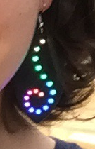
Animation examples
Rainbow that flows if the earring detects a rotation
A light-snake activated by motion
A “Gaussian packet” of light travels along the LEDs when motion is detected.
void cyanspiralsnail() {
  uses_IMU = true;
  uses_framebuffer = true;

  static float snail_location = 2;
  static float motion_measure = 0;

  if (da > 10) { // `da` is a measure of the derivative of the norm of the acceleration
    motion_measure = 1;     // abruptly increase the speed of the snake
  }
  else {
    motion_measure *= 0.99; // slowly decrease the speed if no motion is detected
  }

  static unsigned long time_last_change = 0;

  if (millis()-time_last_change > (20/motion_measure)) { // if enough time has passed (depending on the desired
    clearframe();                                        // snake speed) update the snake "location"
    snail_location += .3;
    snail_location = snail_location - floor(snail_location/16)*16;
    time_last_change = millis();
  }

  for (int i=0; i<16; i++) {                             // set the brightness of each LED depending
    float relative_index = snail_location-i;             // on its distance from the snake "location"
    relative_index = relative_index - floor(relative_index/16)*16;
    if (relative_index>8) {relative_index -= 16;}
    bgr[i][0] = constrain(7.1-0.5*relative_index*relative_index, 0, 7);
    bgr[i][1] = constrain(7.1-0.5*relative_index*relative_index, 0, 7);
  }
}
A color coded compass
Color depending on orientation with respect to magnetic North, brightness depending on recent motion.
void motioncompass() {
  uses_IMU = true;
  uses_framebuffer = true;
  float r,b,g;
  if (mangle < -PI/3) {     // This sequence of if-else recreates a color wheel
    r=0;                    // where the magnetic orientation is turned into a color.
    b=(mangle+PI)/(PI*2/3); // mangle is the last measured angle of the magnetic field.
    g=1-b;
  }
  else if (mangle < PI/3) {
    r=(mangle+PI/3)/(PI*2/3);
    b=1-r;
    g=0;
  }
  else {
    b=0;
    g=(mangle-PI/3)/(PI*2/3);
    r=1-g;
  }
  uint8_t br = constrain(da*r,0,7); // red
  uint8_t bb = constrain(da*b,0,7); // blue
  uint8_t bg = constrain(da*g,0,7); // green
  uniformframe(br,bg,bb); // set all LEDs to the same brightness
}
Simple motion detection
Turn bright purple if any motion is detected.
void purplemotion() {
  uses_IMU = true;
  uses_framebuffer = true;
  uint8_t b = constrain(da,0,7); // da is a measure of the change of the magnintute of the acceleration
  uniformframe(b,0,b);
}
The battery level
Lastly, there is a battery, and an animation mode dedicated to visualizing the current charge level.
The code for all of this can be downloaded here.